What is Energy Meter?
An energy meter is a device that measures the amount of electrical energy used by a home, business, or other building. It is typically installed by the electric utility company, and it is used to measure the amount of electricity that is consumed over a certain period of time, such as a month.
The energy meter is usually located on the outside of the building, near the point where the electrical service enters the building. It is typically a small, rectangular box with a dial or digital display that shows the amount of electricity that has been used. The energy meter is an important tool for electric utilities, as it allows them to accurately bill customers for the electricity that they use. It is also useful for homeowners and business owners, as it allows them to track their electricity usage and identify ways to reduce their energy consumption.
There are two main types of energy meters: induction type and digital type. Induction type energy meters are the most common and are used to measure alternating current (AC) energy consumption. They work by using electromagnets to measure the flow of electricity through a circuit. Induction type energy meters come in two varieties: single phase and three phase. Single phase energy meters are used to measure energy consumption in circuits with a single phase of electricity, while three phase energy meters are used to measure energy consumption in circuits with three phases of electricity. Digital energy meters, on the other hand, use electronic components to measure energy consumption and typically offer more advanced features, such as the ability to record and display real-time energy consumption data.
Construction of Single-Phase Induction Type Energy Meter:
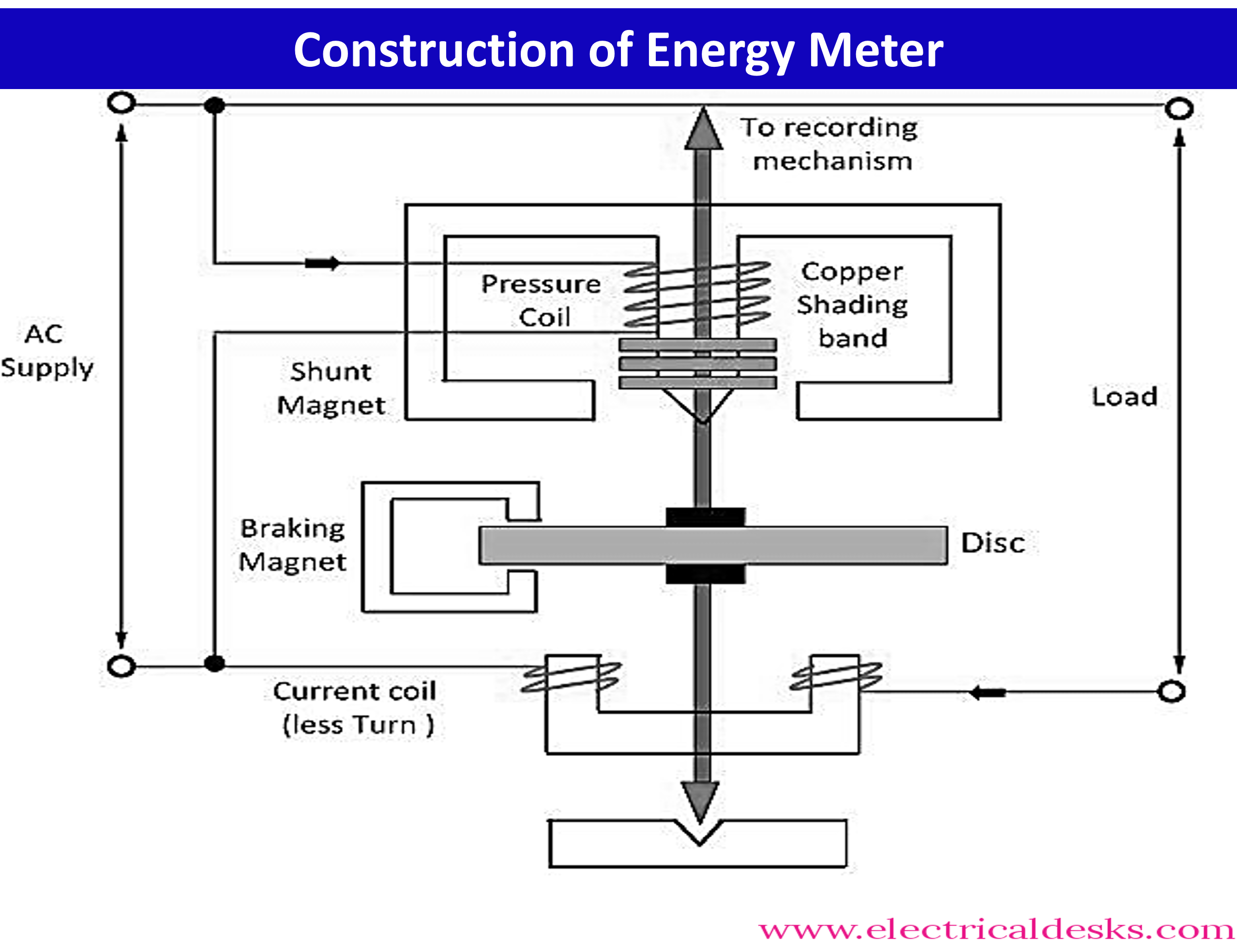
The construction of the Single-Phase Induction Type Energy meter is shown in the below diagram.
The meter consists of four major parts namely,
- Driving system
- Moving system
- Braking system
- Registering system
1. Driving System:
The driving system of an induction type energy meter is responsible for providing the rotational force to the meter's moving parts. It consists of two electromagnets called the shunt magnet and the series magnet. The shunt magnet is magnetized in proportion to the supply voltage, while the series magnet is magnetized in proportion to the load current. The winding of the shunt magnet's central limb is called a pressure coil, and the winding of the series magnet is called a current coil.
The shunt magnet provides a low reluctance path for circulating fluxes, allowing only a small amount of flux to flow through the central limb to the disc. This flux, called Φp, is one of the operating fluxes used by the meter. The second operating flux, Φs, is produced by the series magnet.
In order for the flux Φp to be in quadrature (90° out of phase) with the supply voltage, copper-shading bands or rings are placed on the central limb of the shunt magnet. These bands can be adjusted in order to compensate for any deviations caused by the resistance of the pressure coil and iron losses in the magnetic circuit. This helps to ensure that the meter is operating accurately.
2. Moving System:
The moving system of an induction type energy meter is responsible for measuring the energy being consumed. It consists of a rotor (a lightweight aluminum disc) that is mounted on a shaft and positioned in the air gap between the two electromagnets of the driving system. The rotor rotates at a speed proportional to the energy being measured.
The shaft of the rotor is supported by two bearings: a jewel bearing at the bottom and a sleeve pin-type bearing at the top. These bearings allow the shaft to rotate smoothly and with minimal friction.
The shaft of the rotor also carries a small gear, called a pinion, which connects the shaft to the registering mechanism. The registering mechanism is responsible for displaying the energy consumption being measured and typically consists of a series of gears and indicators. As the rotor rotates, the pinion turns the gears of the registering mechanism, causing the indicators to rotate and display the total energy consumed.
3. Braking System:
The braking system of an induction type energy meter is responsible for controlling the speed of the rotor (disc) and bringing it to a stop when the load is disconnected. It consists of a permanent magnet called a braking magnet that is placed so that the rotor is positioned between its poles.
As the rotor rotates, it cuts through the field of the braking magnet. This causes an induced electromotive force (emf) to be created in the rotor, which in turn causes eddy currents to flow. These eddy currents set up a field in the rotor that opposes the main field of the braking magnet, reducing its magnitude. As a result, a braking torque is produced that opposes the rotation of the rotor, slowing it down.
The braking system is used to maintain a constant torque on the rotor, which allows the meter to accurately measure energy over a wide range of flow rates. It is also used to bring the rotor to a stop when the load is disconnected, allowing the meter to accurately measure energy consumption even when the load is not constantly consuming energy.
4. Registering System:
The registering system, also known as the counting system, is a mechanism in an induction type energy meter that is used to display the total amount of energy consumed. It is connected to the pinion (gear) mounted on the shaft of the rotor and consists of a train of gears.
As the rotor rotates, the pinion turns the gears of the registering mechanism. The gear-turn ratio between the gears is selected so that the indicators on the panel rotate to indicate the total energy consumed. For example, the gear-turn ratio may be set to 10:1, which means that for every 10 rotations of the rotor, the indicators on the panel will rotate by 1 unit. This allows the meter to measure energy consumption up to thousands of kilowatt-hours (kWh).
The registering system may consist of mechanical indicators, such as dials or pointers, or it may use a digital display to show the energy consumption in real-time. The type of display used will depend on the specific energy meter being used.
Working of Single-Phase Induction Type Energy Meter:
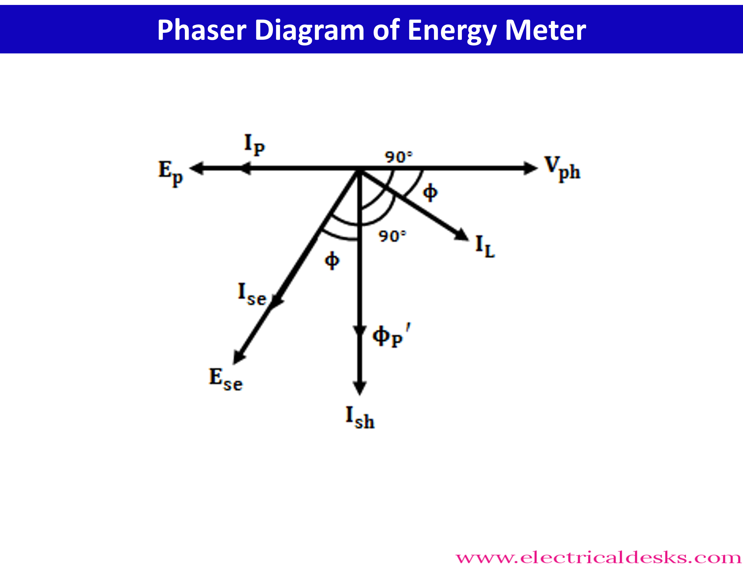
When the load is not connected, there is no current flowing through the current coil of the series magnet, so the magnet is not magnetized, and no flux is produced. In this case, only the shunt magnet is magnetized, producing an alternating flux called Φp. This flux links with the rotor (disc) and induces an electromotive force (emf) called Ep in the disc. As a result, an eddy current called Ip flows in the disc, creating a field called Φp' within the disc.
However, because the fluxes Φp and Φp' are 180° out of phase with each other, they do not produce any torque on the rotor. This means that the rotor will not rotate when the load is not connected.
When the load is connected and a load current (IL) flows through the current coil of the series magnet, the magnet becomes magnetized, and an alternating flux called Φs flows through it. This flux links with the rotor and produces an emf called Ese, which in turn causes an eddy current called Ise to flow in the disc. This current creates a field called Φse' within the disc.
The interaction between the fields Φp' and Φse' causes a torque to be produced on the rotor, which causes it to rotate. The amount of torque produced is proportional to the difference between the torques produced by Ip and Ise. As the rotor rotates, it turns the gears of the registering mechanism, which displays the total energy consumed.
Torque Equation of single Phase energy Meter:
Phaser diagram of energy meter shown in the below diagram
Average Torque of energy meter Given by
∴ T ∝ ΦpIseCosΦ
- ΦseIp cos (180 – Φ)
Where T = average torque produced in the disc
Φp = alternating flux links with the disc
Ise = Eddy current
flowing through the series
Where Cos(180-Φ) = -cosΦ put this in above formula
Above Formula become
∴ T ∝ ΦpIseCosΦ
+ ΦseIp cosΦ
∴ T ∝ CosΦ (ΦpIse
+ ΦseIp )
But given that
∴ Ip ∝ Φp
∝ Vph
∴ Ise ∝ φse
∝ IL
From This
∴ ΦpIse ∝ Vph IL = ΦpIse =A Vph
IL and
∴ ΦpIse ∝ Vph
IL = ΦpIse
= B Vph IL
∴ T ∝ (A Vph
IL + B Vph
IL) cosΦ
∴ T ∝ (A + B ) Vph IL cosΦ
Where A + B = Constant
∴ T ∝ Vph IL cosΦ
In an energy meter, the average torque produced in the disc
is used to measure the power consumed in the load.
The torque produced by the braking magnet (TB) is also
proportional to the speed of the disc (N). The braking magnet applies a force
to the disc to slow it down or stop it from rotating, and the strength of this
force is influenced by the speed of the disc. As the disc speeds up, the
braking magnet must apply a stronger force to bring the disc to a stop.
∴ TB ∝ N
∴ TB = K2 N
∴ T ∝ Vph IL cosΦ
∴ T = K1
Vph IL cosΦ
In a steady-state condition, the braking torque and the
driving torque of an energy meter should be equal.
∴ TB = T
∴ K2 N = K1 Vph IL cosΦ
∴ N = K1/ K2 Vph IL cosΦ
∴ N = True power of the circuit
Advantages of Induction Type Energy Meter:
- Long lifespan with low maintenance: Induction type energy meters are known for their long lifespan and low maintenance requirements. They can be used for extended periods of time without needing frequent repairs or maintenance.
- Inexpensive: Induction type energy meters are generally less expensive than other types of energy meters, making them a cost-effective choice for many applications.
- High torque-to-weight ratio: The induction type energy meter has a high torque-to-weight ratio, which means that it is able to produce a lot of torque while still being relatively lightweight. This makes it suitable for a wide range of applications.
Disadvantages of Induction Type Energy Meter:
- Sensitive to adjustments: If the meter is not properly adjusted, it can introduce large errors in the readings. This can affect the accuracy of the energy measurement.
- Limited to ac measurement: The principle of induction that is used in induction type energy meters can only be applied to alternating current (ac) measurements. This means that these meters are not suitable for measuring direct current (dc) energy consumption.
- Wide range of load measurement: Induction type energy meters are able to measure energy over a wide range of loads, making them suitable for use in a variety of different environments and applications.


