
What is Neutral Grounding?
Neutral grounding refers to the process of connecting the neutral point of a power supply system, rotating machine, or transformer to the earth directly or through some circuit elements. 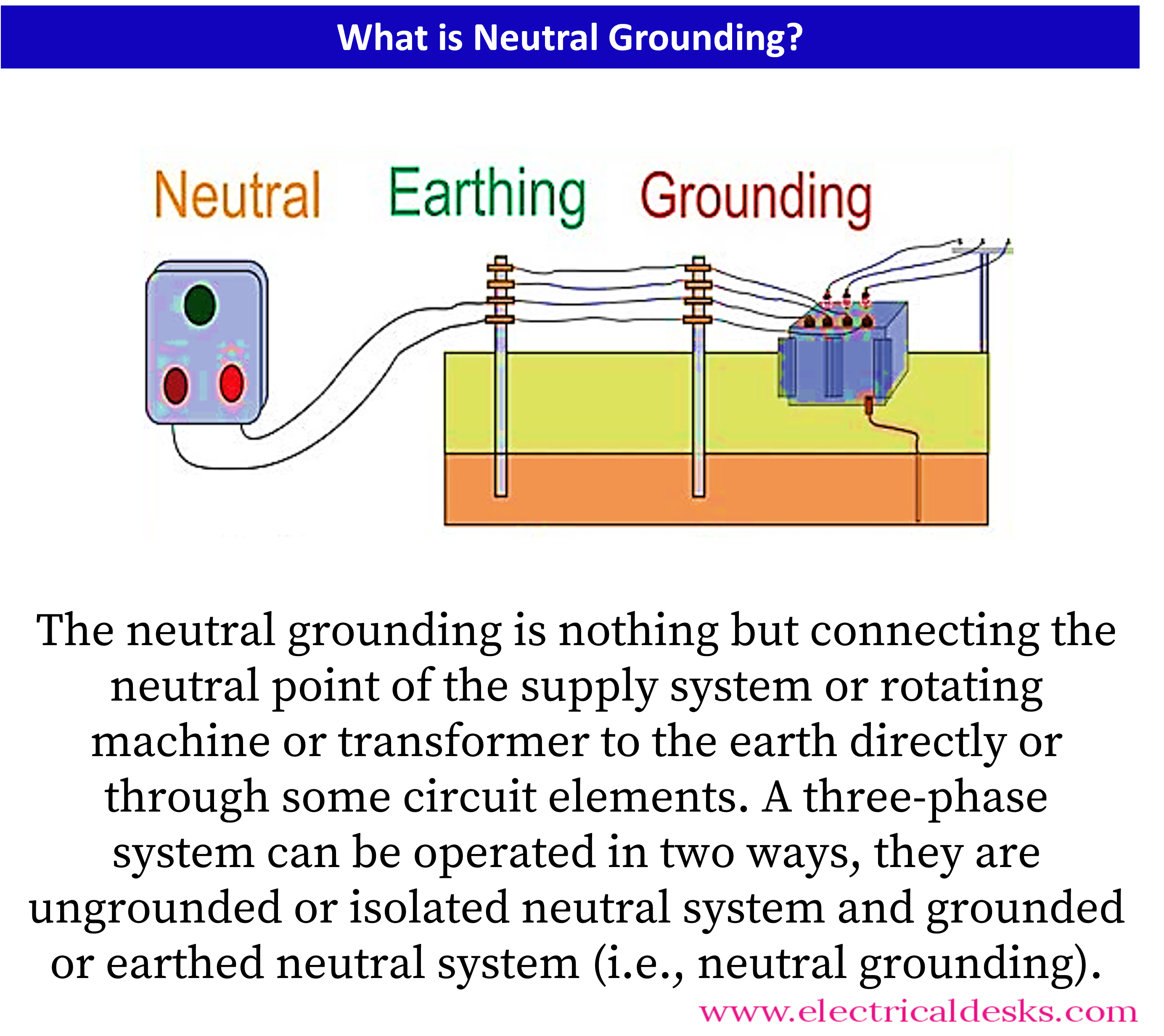
In a three-phase system, there are two ways in which it can be operated:
1. Ungrounded or isolated neutral system and
2. Grounded or earthed neutral system.


1. An ungrounded or isolated neutral system:
An ungrounded or isolated neutral system is a power system where the neutral point is not connected to the earth. This means there is no low-impedance path for the fault current to flow in case of a single-phase fault. Instead, a capacitive coupling exists between conductors and between each conductor and the earth.
There are several disadvantages associated with an ungrounded neutral system, including:
- Insulation breakdown and heavy phase-phase fault conditions: Under a single line to ground fault, the voltage to earth of healthy phases becomes the full line value, leading to insulation breakdown and heavy phase-phase fault conditions. This can be a safety hazard and can cause significant damage to equipment.
- Arcing ground faults: Arcing ground faults can occur in an ungrounded system, which can be dangerous and can damage equipment.
- Difficulty in detecting earth faults: Since there is no low impedance path for the fault current to flow, detecting earth faults in an ungrounded system can complicate earth fault relay.
- Voltage surge due to lightning: In an ungrounded system, voltage surges due to lightning strikes cannot find a path to earth to discharge, leading to damage to equipment in the power system.
Neutral Grounding or Grounded Neutral System :
Need for Neutral Grounding:
There are several reasons why neutral grounding is necessary for power systems.
- One of the main reasons is to provide a path for fault currents to flow to the ground, which helps protect equipment and personnel from electrical hazards. When a fault occurs in an ungrounded system, the fault current will continue to flow until it finds a ground, potentially causing damage to equipment and posing a safety risk.
- Another reason for neutral grounding is to limit the voltage rise that occurs during a fault. When a fault occurs, the voltage of the affected phase will increase due to the impedance of the fault path. By grounding the neutral, the voltage of the affected phase can be limited to a safe level, reducing the risk of damage to equipment and improving system reliability.
Neutral grounding is typically implemented using a grounding resistor or a grounding transformer. The grounding resistor is connected between the neutral point of the system and the ground, creating a low-impedance path for the fault current to flow. On the other hand, the grounding transformer is connected between the neutral point and the ground and provides a way to control the voltage level during a fault.
Advantages of Neutral Grounding:
- The neutral point remains stable under all conditions.
- The voltage of healthy phases concerning the earth remains at normal value, reducing the risk of damage to equipment.
- The system's insulation life is long, reducing maintenance, repairs, and breakdowns.
- Voltage surges caused by arcing grounds are eliminated, improving the continuity of supply.
- Overvoltages due to static-induced charges and lightning surges are discharged to earth without causing disturbances.
- Arcing grounds are extinguished, preventing overvoltage surge due to arcing grounds.
- Earth fault current available is sufficient to operate the earth fault relay, simplifying operation.
- Discriminative type protective gear can be installed.
- Earth fault current can be controlled by employing resistance or reactance in the neutral ground circuit.
- Service reliability is improved, and unnecessary tripping of circuit breakers is prevented.
- Safety of personnel and equipment is increased due to the operation of fuses or relays on ground faults and the limitation of voltages.
- Improved life of equipment, machines, and installation is achieved due to the limitation of voltage.
- Reduction in voltage stress on equipment due to the elimination of overvoltages and voltage surges.
- Enhanced system stability and better power quality.
- Improved fault detection and localization capabilities.
Types of Neutral Grounding:
Solid Grounding:
A solid grounding system is a type of grounding system where the neutral of a power transformer or generator is directly connected to the ground through a conductor with negligible resistance and reactance. This means that the neutral point is effectively held at a neutral potential under all conditions.

In a solid grounding system, the earth fault current is limited to a safe level. This is important because a large current can flow through the ground during a fault, which can damage the equipment and pose a safety hazard to personnel. By limiting the earth fault current, the solid grounding system helps to prevent such incidents.
It is also necessary to limit the earth fault current to less than 80% of the three-phase fault current. This is because if the earth fault current is too high, it can cause the voltage of the healthy phases to rise to a dangerous level, which can lead to insulation failure and equipment damage.
Solid grounding is typically used in low-voltage systems, such as 480V and below. It is also commonly used in industrial plants and buildings, where it is important to limit the earth fault current to prevent damage to equipment and ensure personnel safety.
In a solid grounding system, protective devices, such as fuses or circuit breakers, typically clear faults. The protective device operates when the earth fault current exceeds a predetermined value, which is set to ensure that the earth fault current does not exceed the safe limit.
Resistance Grounding:
Resistance grounding is a type of grounding system in which the neutral of a power system is connected to the ground through resistance. The resistance limits the flow of current during a ground fault, ensuring that the fault current is limited to a safe level. The resistance value is carefully chosen based on the system characteristics to ensure that the ground-fault current is limited but still sufficient to operate the ground-fault protection system.

The resistance grounding system is designed to limit the ground fault current to a level that is safe for equipment and personnel. If the fault current is too high, it can damage equipment and cause safety hazards. The resistance value is chosen to ensure that the ground fault current is limited, but still high enough to operate the ground fault protection system.
One of the main advantages of resistance grounding is that it decreases the risk of arcing grounds. Arcing grounds can occur when the fault current is too high and can cause damage to the system. By limiting the fault current, the risk of arcing grounds is greatly reduced.
Resistance grounding also protects the system from transient overvoltages. Transient overvoltages can occur during lightning strikes or other electrical disturbances and can damage equipment. By limiting the fault current, the resistance grounding system protects the system from these overvoltages.
Another advantage of resistance grounding is that it permits ground-fault protection. Ground-fault protection is essential for ensuring the safety of personnel and equipment. By limiting the ground fault current, the resistance grounding system ensures that the ground-fault protection system operates correctly.
Reactance Grounding:
Reactance grounding is a type of grounding system where a reactance is inserted between the neutral and the ground to limit the fault current. The reactance is usually an inductor, which offers resistance to the flow of current and hence limits the fault current.

One of the main advantages of reactance grounding is that it limits the fault current to a relatively low level, thereby reducing the risk of damage to equipment and minimizing the possibility of arc flash hazards. However, it should be noted that the fault current must be high enough to ensure the proper operation of protective devices such as circuit breakers or fuses. In a reactance grounded system, the ground fault current should not be less than 25% of the three-phase fault current to minimize transient over voltages.
Another advantage of reactance grounding is that it provides better protection against ground faults compared to solid grounding, especially in systems with high capacitance to ground. This is because reactance grounding limits the ground fault current, which reduces the likelihood of arcing faults and limits the damage caused by them.
However, reactance grounding has some disadvantages as well. One of the main disadvantages is that it can be difficult to coordinate protective devices such as fuses and relays. This is because the reactance can cause a time delay in the operation of protective devices, which can lead to unwanted tripping or even failure of protective devices in some cases.
Peterson Coil Grounding:
Peterson coil is a type of grounding device that is used to limit the capacitive earth fault current that flows when there is a line ground fault in the power system. It is essentially an iron core reactor that is connected between the transformer neutral and ground. The coil is designed to have a reactance that is selected so that the current through the reactor is equal to the small line charging current that would flow into the line-to-ground fault.

The Peterson coil is designed to have a tapping mechanism so that it can be adjusted to the capacitance of the system. This ensures that the coil is operating at the right level to effectively limit the fault current. The coil is typically rated for a short time of about 5 minutes or is designed to carry its rated current continuously.
The Peterson coil provides several benefits to the power system. One of the most important benefits is that it reduces the transient fault that can occur due to lightning. By limiting the capacitive fault current, the coil minimizes the voltage drop that occurs during a line-to-ground fault. This helps to reduce the chances of damage to the equipment and ensures the continuity of the power supply.
Another important benefit of the Peterson coil is that it helps to minimize the single line-to-ground voltage drops. This is because the coil limits the capacitive fault current, which in turn limits the voltage drop that occurs during a ground fault. By minimizing the voltage drop, the coil ensures that the power system operates at a stable voltage level, which is important for maintaining the safety and reliability of the system.
Voltage transformer grounding or earthing:
Voltage transformer grounding or earthing is a method of grounding or earthing in which the neutral point of the system is connected to the earth through the primary winding of a single-phase voltage transformer. This system provides a very high reactance earthing due to the high impedance of the voltage transformer. The high reactance earthing helps to limit the fault current and prevent damage to the equipment in the event of a fault.
One of the advantages of voltage transformer grounding is that it provides a fault indicator. When an earth fault occurs on any of the phases, it produces a voltage across the relay connected across the secondary voltage transformer. The relay operates and trips the protecting devices connected to it. This isolates the circuit until the fault is eliminated, preventing any further damage to the equipment.
Another advantage of voltage transformer grounding is that it acts as a reflection point for traveling waves passing through the machine winding. These traveling waves cause high voltages in the circuit, which can be detrimental to the equipment. To prevent high voltage buildup, a surge diverter is connected between the neutral point and the earth. The surge diverter provides a path for the traveling waves to be safely dissipated, preventing any damage to the equipment.
However, there are also some disadvantages to voltage transformer grounding. One of the main disadvantages is that it requires a voltage transformer, which adds an additional cost to the system. Additionally, the voltage transformer can introduce errors in the measurement of voltage and current in the system, which can affect the accuracy of protection and metering systems.
Earthing Transformers (zig-zag transformer):
A zig-zag transformer is a type of transformer used for grounding the power system. It is typically used in situations where a high-resistance ground fault is expected or where it is necessary to limit the fault current to a relatively low value. The zig-zag transformer has no secondary winding and is designed to provide a path for the ground fault current to flow to the ground.

The zig-zag transformer has three limbs, and each limb has two identical windings. One set of windings is connected in a star configuration to provide the neutral point, and the other ends of this set of windings are connected to the second set of windings. The direction of current in the two windings on each limb is opposite to each other.
Under normal operating conditions, the total flux in each limb is negligibly small, and therefore the transformer draws a very small magnetizing current. However, under fault conditions, the impedance of the grounding transformer is very low, which allows the fault current to flow through the transformer to the ground.
To limit the fault current, a resistor is connected in series with neutral grounding. This resistor is designed for a short-time kVA rating and is capable of carrying the rated current for a very short time of 10 seconds. This resistor helps to limit the ground fault current to a safe level and protects the system components from damage.
The zig-zag transformer also terminates the harmonics of the power system. Harmonics are unwanted frequency components that can cause distortion in the system voltage and current waveforms. The zig-zag transformer helps to eliminate these harmonics and maintain a stable power supply.
In addition to limiting fault currents and terminating harmonics, the zig-zag transformer also protects the power system by reducing the stress on the voltage under a fault condition. When a ground fault occurs, the voltage in the system can become very high, which can damage the system components. The zig-zag transformer helps to reduce this stress and protect the system from damage.